Z88 Motherboard Modifications

Updated 9 April 2007

Internal RAM

         Z88 PCB                          32K                         128K                       512K
    +--------------+                                            +--------------+           +--------------+
POE |1    +--+   32| VCC                                     NC |1    +--+   32| VCC   A18 |1    +--+   32| VCC
A16 |2           31| A15           +--------------+         A16 |2           31| A15   A16 |2           31| A15
A14 |3           30| VCC       A14 |1    +--+   28| VCC     A14 |3           30| CS2   A14 |3           30| A17
A12 |4           29| /WE       A12 |2           27| /WE     A12 |4           29| /WE   A12 |4           29| /WE
A7  |5           28| A13        A7 |3           26| A13      A7 |5           28| A13    A7 |5           28| A13
A6  |6           27| A8         A6 |4           25| A8       A6 |6           27| A8     A6 |6           27| A8
A5  |7           26| A9         A5 |5           24| A9       A5 |7           26| A9     A5 |7           26| A9
A4  |8           25| A11        A4 |6           23| A11      A4 |8           25| A11    A4 |8           25| A11
A3  |9           24| /OE        A3 |7           22| /OE      A3 |9           24| /OE    A3 |9           24| /OE
A2  |10          23| A10        A2 |8           21| A10      A2 |10          23| A10    A2 |10          23| A10
A1  |11          22| /CE        A1 |9           20| /CS1     A1 |11          22| /CS1   A1 |11          22| /CS
A0  |12          21| D7         A0 |10          19| D7       A0 |12          21| D7     A0 |12          21| D7  
D0  |13          20| D6         D0 |11          18| D6       D0 |13          20| D6     D0 |13          20| D6  
D1  |14          19| D5         D1 |12          17| D5       D1 |14          19| D5     D1 |14          19| D5  
D2  |15          18| D4         D2 |13          16| D4       D2 |15          18| D4     D2 |15          18| D4  
VSS |16          17| D3        VSS |14          15| D3      VSS |16          17| D3    VSS |16          17| D3  
    +--------------+               +--------------+             +--------------+           +--------------+

Original pseudostatic RAM:      NEC     D42832C-12L
                                               -15L

Tested static RAM:              Hyundai HY62256ALP-10       Mitsubishi M5M51008AP-70    Hitachi HM628512LP-70
                                Hyundai HY62256ALP-70       BSI BS62LV1024PC-70
                                Hitachi HM62256LP-10        Tested by Per Svensson.
                                NEC     D43256C-12L
                                Samsung KM62256BLP-10
                                Sony    CXK58257AP-10L
                                Toshiba TC55257PL-12

Untested static RAM:                                        NEC     µPD431000A          Samsung KM684000
                                                            Samsung KM681000            BSI BS62LV4001PC-70
                                                            Toshiba TC551001

Untested NV RAM:                Simtek  STK15C88-W45        Simtek  STK25CA8
                                Ramtron FM1808-70-P                              New 9 April
                 

Internal ROM

        Z88 PCB          128K mask ROM compatible EPROM      128K mask ROM       
    +--------------+            +--------------+                                  
VCC |1    +--+   32| VCC    VPP |1    +--+   32| VCC                              
ROE |2           31| VCC    /OE |2           31| /PGM       +--------------+      
A15 |3           30| VCC    A15 |3           30| NC     A15 |1    +--+   28| VCC  
A12 |4           29| A14    A12 |4           29| A14    A12 |2           27| A14
A7  |5           28| A13    A7  |5           28| A13    A7  |3           26| A13  
A6  |6           27| A8     A6  |6           27| A8     A6  |4           25| A8   
A5  |7           26| A9     A5  |7           26| A9     A5  |5           24| A9   
A4  |8           25| A11    A4  |8           25| A11    A4  |6           23| A11  
A3  |9           24| A16    A3  |9           24| A16    A3  |7           22| A16  
A2  |10          23| A10    A2  |10          23| A10    A2  |8           21| A10  
A1  |11          22| CE     A1  |11          22| /CE    A1  |9           20| /CE
A0  |12          21| D7     A0  |12          21| D7     A0  |10          19| D7   
D0  |13          20| D6     D0  |13          20| D6     D0  |11          18| D6   
D1  |14          19| D5     D1  |14          19| D5     D1  |12          17| D5   
D2  |15          18| D4     D2  |15          18| D4     D2  |13          16| D4   
VSS |16          17| D3     VSS |16          17| D3     VSS |14          15| D3   
    +--------------+            +--------------+            +--------------+      

Original                      NEC     µPD27C1000D-20          NEC D23C1000

Tested                        Intel   D27C100 (Of 10 tested 1 or 2 seems to work unreliably in the Z88)

Untested                      Hitachi HN27C301G-20
                              Toshiba TC571001D-20
                              AMD     27C100


JEDEC compatible EPROMs

          128K                        256K                        512K
    +--------------+            +--------------+            +--------------+
VPP |1    +--+   32| VCC    VPP |1    +--+   32| VCC    VPP |1    +--+   32| VCC
A16 |2           31| /PGM   A16 |2           31| /PGM   A16 |2           31| A18
A15 |3           30| NC     A15 |3           30| A17    A15 |3           30| A17
A12 |4           29| A14    A12 |4           29| A14    A12 |4           29| A14
A7  |5           28| A13    A7  |5           28| A13    A7  |5           28| A13
A6  |6           27| A8     A6  |6           27| A8     A6  |6           27| A8
A5  |7           26| A9     A5  |7           26| A9     A5  |7           26| A9
A4  |8           25| A11    A4  |8           25| A11    A4  |8           25| A11
A3  |9           24| /OE    A3  |9           24| /OE    A3  |9           24| /OE
A2  |10          23| A10    A2  |10          23| A10    A2  |10          23| A10
A1  |11          22| /CE    A1  |11          22| /CE    A1  |11          22| /CE
A0  |12          21| D7     A0  |12          21| D7     A0  |12          21| D7
D0  |13          20| D6     D0  |13          20| D6     D0  |13          20| D6
D1  |14          19| D5     D1  |14          19| D5     D1  |14          19| D5
D2  |15          18| D4     D2  |15          18| D4     D2  |15          18| D4
VSS |16          17| D3     VSS |16          17| D3     VSS |16          17| D3
    +--------------+            +--------------+            +--------------+
     Hitachi 27C101                                          Hitachi 27C4001
     ST M27C1001                 ST M27C2001                 ST M27C4001


JEDEC compatible Flash EPROM

                                                                  512K
                                                            +--------------+
                                                        A18 |1    +--+   32| VCC
                                                        A16 |2           31| WE
                                                        A15 |3           30| A17
                                                        A12 |4           29| A14
                                                        A7  |5           28| A13
                                                        A6  |6           27| A8
                                                        A5  |7           26| A9
                                                        A4  |8           25| A11
                                                        A3  |9           24| /OE
                                                        A2  |10          23| A10
                                                        A1  |11          22| /CE
                                                        A0  |12          21| D7
                                                        D0  |13          20| D6
                                                        D1  |14          19| D5
                                                        D2  |15          18| D4
                                                        VSS |16          17| D3
                                                            +--------------+
                                                              AMD Am29F040         New 9 April

Motherboard Modifications

PCB track modifications.
Component side of board.

To use JEDEC EPROM for internal ROM:

Disconnect IC3 pin 2 from the ROE track by cutting it in two places on the component side of the board.
The adjacent A16 track is shown for clarity because the view is usually obscured by a socket.
Disconnect IC3 pin 24 from the A16 track by cutting it on the solder side of the board.
Connect IC3 pin 24 to the ROE pad close to IC3 pin 17.
Connect the ROE pad close to IC3 pin 31 to the ROE track going to SLOT 1.
Connect IC3 pin 2 to the A16 track going to SLOT 2.

To use 256K JEDEC EPROM for internal ROM:

Also disconnect IC3 pin 30 from VCC by cutting the track from pin 31.
Connect IC3 pin 30 to the A17 track going to slot 2 pin 36.
128K JEDEC EPROM should still work but is not tested.

To use 512K JEDEC EPROM for internal ROM:

Also disconnect IC3 pin 31 from VCC by cutting the track from pin 32.
Connect IC3 pin 31 to the A18 track going to slot 2 pin 37.
Not sure if 128K or 256K JEDEC EPROM can be used after this modification because of pin 31 /PGM.
For layout of code on larger than 128K internal ROMs see:
Z88 Internal ROM Modifications

To use 512K JEDEC Flash EPROM for internal ROM:

Also disconnect IC3 pin 31 from VCC by cutting the track from pin 32.
Disconnect IC3 pin 1 from the VCC track by cutting it close to the pad at pin 1.
Connect the VCC pad close to IC3 pin 8 to the VCC track going to SLOT 2 pin 21.
Connect IC3 pin 1 to the A18 track going to slot 2 pin 37.
Connect IC3 pin 31 to the pad between IC3 pin 1 and 32 on the WE track going to slot 2 pin 22.
Not sure if 128K or 256K JEDEC EPROM can be used after this modification because of pin 31 /PGM and pin 1 VPP. New 9 April
For layout of code on larger than 128K internal ROMs see: Z88 Internal ROM Modifications

PCB track modifications.
Solder side of board.

To use 128K static RAM for internal RAM:
No track changes needed.

To use 512K static RAM for internal RAM:

Disconnect IC2 pin 30 from the VCC by cutting the track from pin 32.
Connect IC2 pin 30 to A17 at slot 2 pin 36.
Disconnect IC2 pin 31 from the /PGM track by cutting it close to the pad near pin 1 and 2.
Connect the IC2 pin 31 to A18 at slot 2 pin 37.
Not sure if 128K static RAM can be used after this modification because of pin 30 CS2.
Desoldering multi-pin chips is difficult. To make it easier, cut all pins close to the chip and unsolder them one at a time.

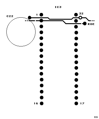
Installing the chips in a socket is recommended. A low profile socket is a must. Even so, the keyboard reaction plate may have to be cleared of reinforcement webs like it is above the ROM chip.

There are ultra low sockets that makes the RAM chip fit without clearing the reinforcements. Tested by Per Svensson.


mailto address


Back to Cambridge Computer Z88